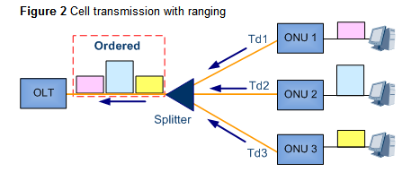
The logic reaches from optical network units (ONUs) to an optical line terminal (OLT) vary. The round trip delays (RTDs) between an OLT and ONUs also vary depending on time and environment. Therefore, collisions may occur when ONU sends data in TDMA mode (in this mode, only one of the ONUs connecting to a PON port sends data at a moment), as shown in Figure 1.

To prevent the collisions, ranging is enabled when an ONU (HG8245) registers for the first time. The OLT (MA5683T) measures the RTD of each ONU in the ranging process and calculates the equalization delay
(EqD) of each ONU to ensure that the values of Teqd, which is equal to RTD plus EqD, of all
ONUs connected to the same PON port are the same. Therefore, the logic reaches from ONUs
to an OLT are the same, preventing collisions during upstream transmission.
Burst Optical/Electrical Technology
In 10G GPON upstream direction, Time Division Multiple Access (TDMA) is used. An optical
network unit (ONU) transmits data only within the allocated timeslots. In the timeslots that are not allocated to it, the ONU disables the transmission of its optical transceiver to prevent other
ONUs from being affected. The optical line terminal (OLT) then receives the upstream data
from each ONU in a burst manner based on timeslots. Therefore, to ensure normal running of
the 10G GPON system.

Ranging can be implemented to prevent cells transmitted by different ONUs from conflicting
with each other on the OLT. However, the ranging accuracy is ± 1 bit and the cells transmitted
by different ONUs have a protection time of several bits (not a multiple of 1 bit). If the ONU-
side optical modules do not support the burst transmit function, the transmitted signals overlap
and distortion occurs.

- The distance from each ONU to the OLT varies and therefore the optical signal attenuation varies for each ONU. As a result, the power and level of packets received by an OLT at different timeslots various.
- If the OLT-side optical modules do not support the burst receive function, the OLT may restore incorrect signals because only the level greater than the threshold is considered valid and the signals with the level lower than the threshold cannot be restored.
DBA
The OLT uses DBA to dynamically adjust the upstream bandwidth allocated to different ONUs
to address the burst traffic on the ONUs, meeting the ONU upstream bandwidth requirements
and improving the utilization of the PON upstream bandwidth.

In the preceding figure,

- The DBA module in the OLT consistently collects DBA reports and uses the DBA algorithm to calculate the upstream bandwidth allocated to each ONU.
- The OLT sends the calculated result to each ONU using a bandwidth (BW) map.
- Each ONU transmits burst upstream data using permitted timeslots defined in the BW map.

Highlights and Applications
- Based on ONUs' burst upstream service traffic, the OLT dynamically allocates an upstream bandwidth to each ONU in real time, improving upstream bandwidth utilization on PON ports.
- More users are supported on a PON port.
- Higher service bandwidths with burst requirements are supported than those before DBA is applied.
Forward error correction (FEC) is mainly used for improving transmission
quality of a line.
No ideal digital channel is available in practice. As a result, bit errors and jitter occur when digital signals are being transmitted over any transmission medium, deteriorating transmission quality on lines.
No ideal digital channel is available in practice. As a result, bit errors and jitter occur when digital signals are being transmitted over any transmission medium, deteriorating transmission quality on lines.
To resolve the problem, error correction mechanism is introduced.
- The mechanism can check and correct errors after data is transmitted to the peer end. such as FEC.
- The mechanism can check errors after data is transmitted to the peer end but not correct errors.
Highlight and Application
- Does not require retransmission and provides a high real-time performance
- Requires an additional bandwidth (Users must balance the transmission quality and bandwidth.)
- Checks and corrects errors after data is transmitted to the peer end, but does not apply to services for which retransmission is enabled
- Applies to data transmission on the network that has a poor quality
- Applies to services that have a low requirement on delay (The delay is large if retransmission is configured for services.)
Configuration Guide
The FEC function of 10G GPON as follows:
- Supported only in the downstream direction.
- FEC is enabled by default.
- The FEC function cannot be configured manually.
More related:


